Learning Visual Feedback Control for Dynamic Cloth Folding — What The Paper Does Not Tell You — Part 2 — The Controller
This is the second part of a technical report to provide more background on the design choices made in our paper “Learning Visual Feedback Control for Dynamic Cloth Folding”. Image by the author.
In this series of blog posts, we are delving into the technical challenges involved in creating our paper “Learning Visual Feedback Control for Dynamic Cloth Folding”, which was accepted for publication at the 2022 IEEE/RSJ International Conference on Intelligent Robots and Systems (IROS 2022) and was a finalist for the Best Paper Award.
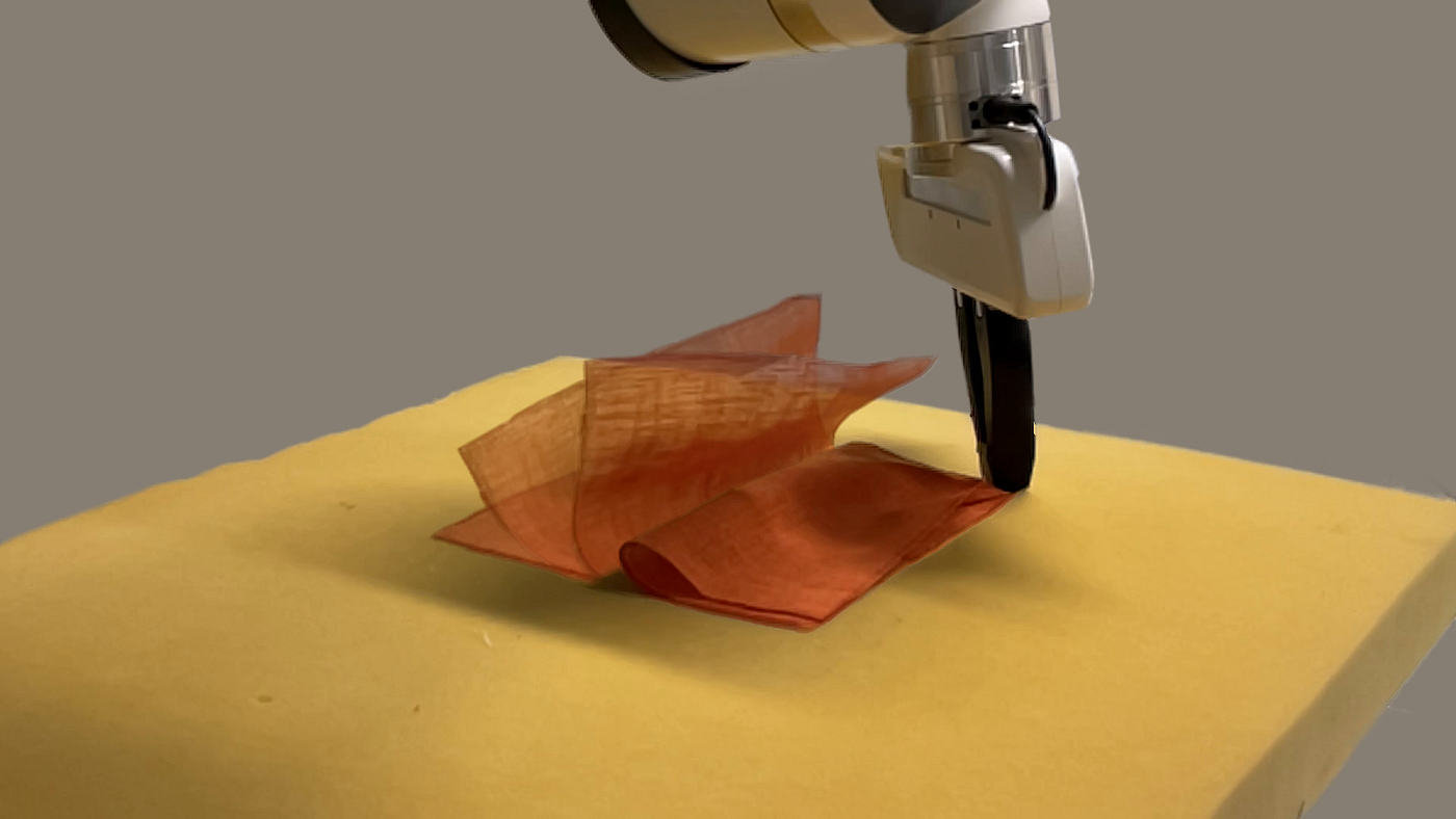
Robotic cloth manipulation has the potential to revolutionize a variety of industries by improving the efficiency and productivity of tasks such as manufacturing, bed making, and changing linens. However, it is a difficult task due to the variability of materials and the complexity of cloth dynamics.
One way to train robots to manipulate cloth is through the use of Reinforcement Learning (RL) in simulation, but there is a challenge known as the “Sim2Real gap” in transferring these skills to the real world. In our paper, we trained an RL model using a robot and visual feedback to dynamically fold various pieces of fabric, addressing the Sim2Real gap by using techniques such as visual feedback and domain randomization to help the robot adapt to the real-world environment.
In this follow-up blog post, we will delve into the development of the controller that was used to guide the robot in both simulation and the real world, allowing for the successful folding of various pieces of fabric.
Deciding the action space
Given that we were able to verify and validate camera sensor latency and the required feedback frequency of the RL task, the next requirement related to controlling the robot was that the outputs of the RL policy should not only achieve the dynamic cloth folding task but also be intuitive for a human to analyze and impose constraints on the actions if needed.
An action space in Cartesian coordinates was therefore a natural choice, where the actions can be understood intuitively and the new desired position of the gripper is a simple function of the current gripper position and the 3D action output by the RL policy.
The above is compared to an action space in joint space, where the resulting desired gripper position is a non-intuitive function of the current joint configuration and/or the actions in joint space. Allowing the RL policy to control the robot in joint space in simulation might work in terms of successful learning, but not being able to intuitively understand the expected behavior in the real world is very undesirable and hard to debug in case there is an issue in the Sim2Real transfer.
Initial controller testing
We used the Robosuite library to run initial tests to find a suitable controller. The specific controllers we tested were Operational Space Control (OSC) and a basic inverse kinematics (IK) controller.
Based on initial simulation experiments comparing the two controllers, it was evident that using OSC achieved movement of the robot that was much more intuitive and reactive compared to IK. On a high level, the OSC framework computes the required joint torques with the minimum kinetic energy of the gripper to minimize the error between the current and desired position and orientation of the robot gripper.
Given that the OSC in Robosuite was in Python, we had to reimplement it using C++ to be used with real hardware. Identical logic of the controller was created in a single C++ header file for a single controller time step, which could then be called from the main controller loop. The main controller loop was implemented using ROS and its ros_control package, which provides an easy-to-use interface to the real robot’s internal controller.
The controller loop also made use of the franka_ros library, which enables interaction with the real robot’s hardware using ROS. The utility packages RViz and dynamic_reconfigure were also used in the implementation, which allowed us to visualize and move the desired position of the gripper and other parameters while the controller was running.
Validating the controller
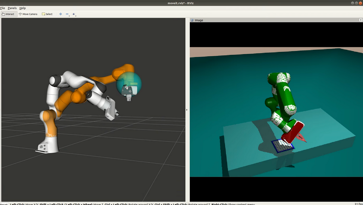
An RViz interface to control the robot simulated in MuJoCo. Photo by the author.
The above figure shows the RViz interface which allows changing the desired gripper position using a mouse by moving the blue sphere in 3D. We also tuned the rate at which the desired position of the gripper in the control loop was updated. This was important since too large jumps in the desired position in the control loop would cause very large torques and potentially make the robot move in an unstable way. The desired position in the control loop was updated at each controller time step, illustrated by the sphere shown in the figure.
We also created a version of the control loop, where the desired position could be updated based on incrementing it with desired Cartesian 3D displacement vectors, which could for example be actions from the RL policy or from a predefined trajectory.
Before testing our C++ implementation on real hardware, it made sense to first run it in simulation to see that it worked as expected. Fortunately, previous research in our lab had implemented an interface for using MuJoCo from C++ which allowed reading values such as joint angles, joint velocities, and the inertia matrix and the Jacobian of the robot from the simulation, along with setting torques for the robot joint actuators.
It was therefore easy to implement an alternative interface with the applicable functions and properties of the franka_ros interface, that interacted with the MuJoCo simulation instead of the real robot’s internal controller. This also allowed us to use the same visualization and configuration utilities provided by RViz and dynamic_reconfigure against the simulation, which helped to visually confirm that the controller was working as desired and helped to find approximate values for controller gains.
After fixing some minor bugs encountered during the validation, we were confident enough to use the actual franka_ros interface with the real robot. The controller gains and the filter value of f were further tuned empirically on the real robot so that the movement of the robot happened approximately in real-time when moving the desired position sphere in RViz.
Aligning robot behavior
Since we were able to find controller settings that worked well on the real hardware, the next step was to verify that the simulated robot would behave similarly when using the same controller and settings. One option would have been to use the controller implementation provided by Robosuite directly, but it would have been prone to situations where a minor update somewhere in the control logic would cause discrepancies, and debugging would be painful.
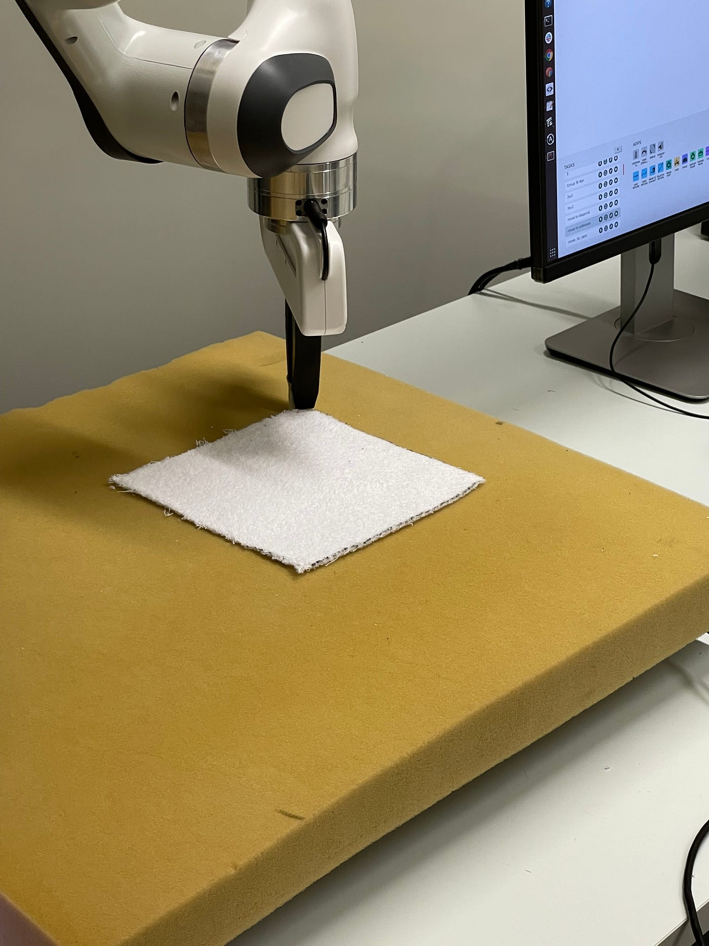
Initial robot configuration for creating validation trajectories. Photo by the author.
Therefore the created OSC control step logic in the C++ header file was wrapped with python using the pybind11 library, which allowed the control step logic to be called directly from the Python simulation environment. A thing to note is that the real-world robot operates at 1kHz whereas the simulation environment runs at 100Hz.
Therefore when running the simulation, the desired position update step was executed 10 times to achieve the same desired position before calculating the needed torque. This was also a potential source of error in the simulated and real environments, where the real robot was fed smaller torque values more frequently, whereas the simulated robot received larger torques less frequently.
Verifying the alignment between simulation and real required then to define a baseline setup in the lab, where the gripper was manually moved to a certain location while having the cloth taped to the gripper. Reproducing the same configuration in the simulation was easy since the joint angle values could easily be read programmatically and then hardcoded into the MuJoCo model to achieve the same starting configuration in the simulation.
The web-based control application for the Franka Emika Panda robot, called Desk, was used to create a workflow that moves the robot to the same desired starting configuration. The image above shows the initial configuration in the lab. The verification proceeded by collecting examples of folding trajectories by moving the robot manually starting from the desired initial configuration and performing successful folds, while a script was running that saved the gripper positions during the movement into a file.
Given the demonstration trajectory log files, displacement vectors were calculated from every 100 logged positions, and used to update the desired gripper positions. This approach was able to produce trajectories almost identical to the demonstrated trajectories, meaning that the controller was tuned properly.
The same interface of feeding vectors into the simulated environment and the controller were already available in RL the environment’s step-function, which allowed executing the same predefined trajectories in simulation as well. The achieved gripper positions in the simulation were logged into a file, so they could be compared to the trajectories achieved by the real robot.
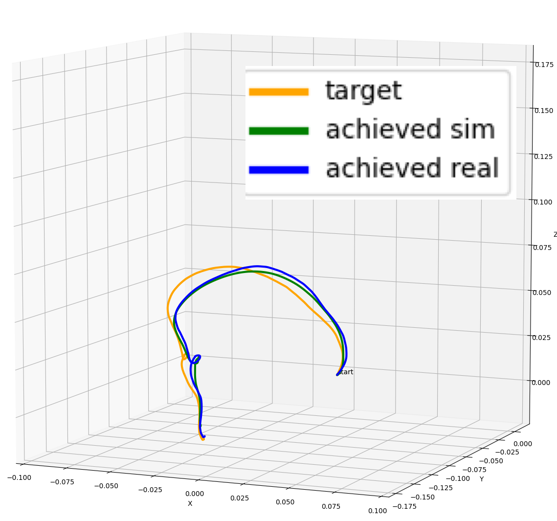
Comparing a desired target demonstration trajectory to trajectories performed by the simulated and real robots. Illustration by the author.
At first, the trajectories followed by the simulated and real robots did not match each other at all, where the simulated robot was reacting slower to the control signal as if it was more damped than the real robot. Tuning the controller’s gain parameters has of course an effect on robot behavior, but the expectation is that regardless of suboptimal parameters, the simulated and real robots should behave similarly.
The initial mismatch then forced us to take a closer look at the MuJoCo model provided by Robosuite. We found out that the authors were using a feature where the inertial properties of the robot are defined using the inertial -element in the XML file. The used parameter values for the links’ masses along with the inertial matrix seemed arbitrary, instead of carefully tuned values.
An option would have been to inquire the authors about the origin of the parameters, but beginning a process of getting better estimates for the values seemed like a tedious task. Fortunately, MuJoCo offers a setting called inertiafromgeom, where the bodies’ inertias are inferred from the geometric elements attached to the body automatically.
The MuJoCo XML documentation mentions that the feature is designed especially for poorly designed models, which have seemingly arbitrary inertias which are too large compared to the mass.
After enabling the inertiafromgeom -feature, the achieved trajectories matched each other fairly closely as seen in the figure above. There was still some disparity between the desired target demonstration and the robots’ actual behavior due to the controller’s gain parameters, but the trajectories the robots perform were close enough to each other.
Conclusion
In this blog post, we discussed the technical challenges involved in developing a controller for a robot to perform dynamic cloth folding in both simulation and the real world.
We compared two different controllers — Operational Space Control (OSC) and inverse kinematics — and found that OSC resulted in more intuitive and reactive movement of the robot, both in simulation and the real world.
In the final edition of this blog series, we will be discussing the use of domain randomization as a method for helping the robot adapt to the real-world environment and bridge the Sim2Real gap.
The links to all of the blog posts in the series can be found here: Part 1, Part 2, and Part 3.